The Gate is a special flow operation that acts as a valve in the flow. It blocks the data flow at a specific point and only releases it when a condition is met. The incoming data is passed through unchanged to the following operation (pass-through).
A typical use case: A specific branch of a flow should only continue once another branch (e.g., a data export) has been completed successfully.
[Source A] --> [Mapping] --> [Gate] --> [Further Processing]

[Source B] --> [Data Destination CSV] ---(on success: trigger Gate)---
Sequence:
- The flow starts, Source A and Source B run in parallel in their branches
- Branch A: Source A -> Mapping -> Gate receives data and stops
- Branch B: Source B -> Data Destination CSV writes successfully
- The data destination is configured as trigger operation -> the Gate opens
- The Gate passes its data through -> “Further Processing” starts
1. Creating a Gate
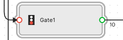
A Gate is dragged from the toolbox in the graphical flow editor onto the canvas, just like any other operation. The Gate is recognizable by its traffic light icon.
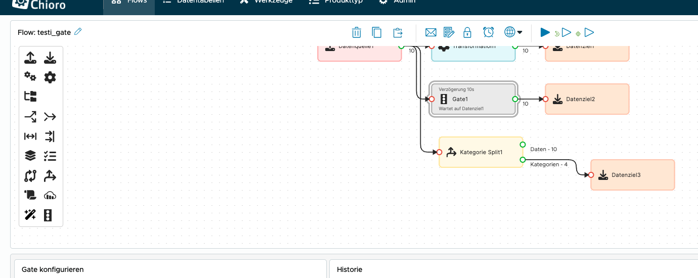
After placing it, the Gate is connected to predecessor and successor operations using arrows. A Gate has exactly one input and one output.
2. Configuring a Gate
After creation, the Gate configuration appears. The Basic tab contains all essential settings:
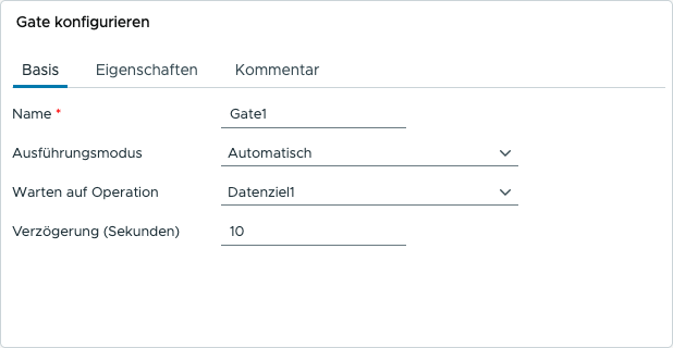
Name- A descriptive name for the Gate.Execution Mode- Determines how the Gate is triggered (see below).Wait for Operation- The operation whose successful completion opens the Gate (only in “Automatic” mode).Delay (seconds)- Optional delay in seconds after triggering before the Gate opens (only in “Automatic” mode).
Execution Mode
The Gate has two modes:
Automatic (Default)
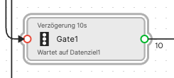
In automatic mode, the Gate is triggered by another operation in the same flow. The triggering operation is selected in the Wait for Operation field. Once this operation completes successfully, the Gate opens automatically (optionally after the configured delay).
On the canvas, an automatic Gate displays the configured delay and the triggering operation as subtitles:
Manual
In manual mode, the Gate is not triggered automatically. It blocks the flow permanently until it is manually opened via the Continue button in the Gate configuration. The “Wait for Operation” and “Delay” fields are not available in this mode.
Manual Gates are indicated on the canvas by a red traffic light:
To open a manual Gate, select it in the flow editor. The Continue button appears above the history:

3. Behavior during flow execution
When a flow with Gates is executed, the following rules apply:
- Gate stops the flow: All operations after a Gate are not started during normal flow execution. The flow branch ends at the Gate.
- Automatic Gate: Triggered once the configured operation completes successfully. After the optional delay, the subsequent operations are started.
- Manual Gate: Only triggered via the Continue button. The flow remains stopped at the Gate until a user intervenes manually.
- Pass-through: The Gate does not transform any data. Incoming data is passed unchanged to the following operation.
- Run from here: Using the context menu of an operation, the flow can be started from a specific point. The flow then runs until the next blocking Gate.
4. History
The Gate’s history shows past executions. For automatic Gates, the configured delay is displayed. For manual Gates, the note “manually started” is shown.